Monday, September 28, 2009

Quick progress update

Been a long time since I blogged here. I have been advising some school kids at a local high school on RepRap which has soaked up my free time and stopped progress on ExMrClean.

We are in the final stretch for getting their RepStrap operational and so it is finally time for me to also get operational so I can hopefully be a step ahead of them for a bit longer LOL!

Anyway one of the resources that they have available to them is a laser cutter and we have been building up an extruder mount out of acrylic to use a mill that they also have access too as the motion platform.


As you can see from the picture they have created a quite intricate structure that will mount up to three extruders and has an option for hanging wingman extruders off to each side.

Here’s a picture with the electronics and some bare PCB’s mounted on the mill.


So anyway back to ExMrClean I requested that they make me a extruder holder for my machine, which they designed and constructed in a couple of hours.


The construction of this design with the mounting screws on the side allowed me to correct for my Z axis not being totally true.

Tuesday, May 12, 2009

Burning AVR boot loader with USB TTL Serial Cable

I am working with some kids at local high school that ordered a Sanguino kit to put together just after Makerbot went online.

The kit was missing some components and others were the wrong size. How ever the big problem was that processor chip did not get the boot strap loader for the Arduino IDE development environment flashed into it.

Generally you use a programmer to burn your target program onto an AVR chip, for the Arduino IDE environment we burn a boot loader that lets us upload new programs into the flash memory via the Arduino IDE.

There are multiple ways to burn the loader that we need. Some of them are:


  • External ISP or JTAG programmer

  • Use the Arduino-IDE via a parallel port and adapter

  • Use another Sanguino or Arduino as a programmer

  • Use the USB Serial cable TTL-232R in bit banger mode

A good article on AVR family programming options is at:

http://www.ladyada.net/library/avrdevtut/programmers.html

I am blogging about the last approach of using the USB Serial cable as it doesn’t require any additional hardware other then what you would normally have to run a Sanguino or Arduino board.

Credit where credit is due I got the basic information and links to the required software from a blog by Kimio Kosaka.

http://www.geocities.jp/arduino_diecimila/bootloader/index_old_en.html

What is bit banger mode?

The USB-Serial chip that is molded into our serial cable and mounted on most Arduino boards that have USB connectors has a mode where software can control the state of the normal serial port signal lines.

The typical USB chip is a FTDI FT232 chip for serial operations. This is not to be confused with RS-232 which is a signal level standard with positive and negative voltages.

Since our USB cable length is short it uses standard TTL voltages between 0 and 5 or 0 and 3.3 depending on which cable you have.

We differ in approach from Kimio Kosaka examples in that we have to remap which software controlled pins are used for programming; as the USB-Serial cable only brings out to the connector four of the eight pins that are used for full serial port control.

If you want to know the terminology of these lines here’s a good link.

http://tldp.org/HOWTO/Serial-HOWTO-20.html

Our USB cable is lacking the following serial port control lines DTR, DSR, RI, DTR, so we have to make use of the ones that we do have available at the connector which are CTS, RTS, TXD and RXD.

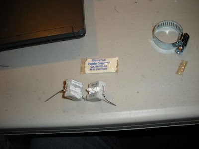
It’s also handy to power the chip up via the voltage delivered by the USB cable. (Note the board that has the chip you are trying to program should not be powered up as it might interfer in the programming process.)

Here’s a link to the documentation for our USB serial port cable.

http://www.ftdichip.com/Documents/DataSheets/Modules/DS_TTL232R.pdf

Downloading the software

The next step is to download the software from the web page above. Here’s the link that I used to download software for windows. The orginal web page also has links for Linux and Mac.

http://www.geocities.jp/arduino_diecimila/bootloader/files/serjtag-0.3.zip


Adding definition to use USB cable as a programmer

After unzipping the content locate the following programmer configuration segment in the avrdude.conf file.

programmer
id = "ft232r";
desc = "FT232R Synchronous BitBang";
type = ft245r;
miso = 1; # RxD
sck = 0; # RTS
mosi = 2; # TxD
reset = 4; # DTR
;

This one is one that is closest to the definition that we need for our USB to serial cable. So we will use it as a template to add our required definitions. The pin assignments we get from the following document.

http://www.ftdichip.com/Documents/AppNotes/AN232B-01_BitBang.pdf

Our resulting programming cable definition is:

programmer
id = "ft232u";
desc = "FT232U USB Cable Synch BitBang";
type = ft245r;
miso = 1; # RxD
sck = 2; # RTS
mosi = 0; # TxD
reset = 3; # CTS
;

Adding support for the ATmega644P chip

The AVRDUDE program that we downloaded with the link above is not the latest release of AVRDUDE. The USB serial chip programming seems to be a branch that has not made it back to the main code base.

Again since this is an older version there is no definition in the avrdude.conf file for the ATMEGA644P chip that we are using for the Sanguino.

So we need to clone the entire section for the ATmega644 and then change the id and the chip signature bytes in the header portion too look like the following fragment:

#------------------------------------------------------------
# ATmega644P
#------------------------------------------------------------
# similar to ATmega164p
part
id = "m644p";
desc = "ATMEGA644P";
has_jtag = yes;
stk500_devcode = 0x82; # no STK500v1 support, use the ATmega16 one
avr910_devcode = 0x74;
signature = 0x1e 0x96 0x0a;

Building the programming cable


The final step is build an adapter cable to plug into the ISCP programming plug here is the pin out mapping for the cable:


Header pin


Name


Color


ISCP pin


ISCP Name


1


GND


Black


6


GND


2


CTS


Brown


5


reset


3


VCC


Red


2


VCC


4


TXD


Orange


4


mosi


5


RXD


Yellow


1


miso


6


RTS


Green


3


sck


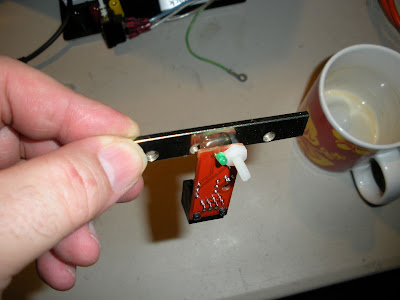
Here's a picture of my adapter cable that I constructed:


Initial testing

After verifying that you have built the cable correctly, test that everything is running correctly by using the following command.

avrdude -c ft232u -P ft0 -p m644p -B 4800

It should result in output that looks like the following:

C:\serjtag-0.3\avrdude-serjtag\binary>avrdude -c ft232u -P ft0 -p m644p -B 4800
avrdude: BitBang OK
avrdude: pin assign miso 1 sck 2 mosi 0 reset 3
avrdude: drain OK

ft245r: bitclk 4800 -> ft baud 2400
avrdude: AVR device initialized and ready to accept instructions

Reading ################################################## 100% 0.00s

avrdude: Device signature = 0x1e960a

avrdude: safemode: Fuses OK

avrdude done. Thank you.


C:\serjtag-0.3\avrdude-serjtag\binary>


If you get the message "avrdude: ft245r_program_enable: failed" then there is probably something wrong with your cable or the changes you have made to your config file.

(Further edit: You might have previously set a fuse to use an external clock that is not working or is the wrong frequency for your target chip. If so you might be able to feed clock signal from a functioning chip or board to reset the fuses.)

Burning the Boot loader into the Sanguino ATmega644P chip

Only proceed to this step if the previous verification command works. Note the -p option selects a paticular chip so using another chip this value and others related to fuzes will change!

I found the necessary syntax for programming the chip on this blog entry, and translated from the Linux example for using it in the windows environment.

http://gorillarobotics.blogspot.com/2009/01/sanguino-burn-bootloader-script.html

From the Sanguino software distribution copy the ATmegaBOOT_644.hex file into your working directory and then issue the following commands.


avrdude -c ft232u -P ft0 -p m644p -U flash:w:ATmegaBOOT_644.hex:i

avrdude -c ft232u -P ft0 -p m644p -B 4800 -U lock:w:0x3F:m -U efuse:w:0xFD:m

avrdude -c ft232u -P ft0 -p m644p -B 4800 -U hfuse:w:0xDC:m

avrdude -c ft232u -P ft0 -p m644p -B 4800 -U lfuse:w:0xFF:m -U lock:w:0x0F:m

Note the first command did not have the "-B 4800" option so it automatically selected a faster data tranfer rate.

If the flash write operation will not verify or you get a RC=1 return code then you will need to select a lower data rate and add it to the command line.

Data rate values are:

-B 4800
-B 9600
-B 19200
-B 28800
-B 38400
-B 115200
-B 230400
-B 460800

Further edits:

Burning other chip types

The instructions in this post are only for the ATmega644P chip! The orginal link above from Kimio Kosaka delt with programming a Arduino Diecimila with a ATMEGA186 chip.

Fuzes vary between the processors, so you need to find an AVRdude example for your chip and usage environment (internal, external oscillator, etc) to get the correct fuze settings.

Also you need to have a bootstrap hex file that is compiled for your processor and oscillator configuration and speed!

The AVRdude program is used with lots of different AVR programmers so the parameter value “-c ft232u” references using USB TTL serial cable in bit banger mode and the “-B 4800” for the programming rate are the primary differences to consider when using other AVRdude examples as a baseline for your enviorment.

Please read comments from other people below as they relate further corrections, sucesses and pitfalls.

Thursday, February 5, 2009

NoGo Extruder


Well I thought I would try a variation on Forests 5/32 tube extruder. My goal was to combine a variation of Forest’s approach along with Demented’s to come up with a hardware store extruder that didn’t require any machining or brazing.

I worked out a variation to Demented’s approach that is easy and I am happy with (more about that in a future post assuming it actually works).

Links to their posts where I got the idea’s from are:

Forest:

http://www.3dreplicators.com/cgi-bin/cblog/index.php?/archives/310-Building-a-new-heated-extruder-barrel-for-the-Mk-1.html

Demented:

http://builders.reprap.org/search?q=Extruder+Madness+Part+Deux%21

Anyway on to passing on what didn’t work.

What I didn’t initially like is that Forest’s extruder was the same Nichrome Wire/JB Bond or other cement, and the fixed one shot nozzle size.

I had what seems to be winner to avoid with my experiment with four five watt resistors.

Here’s my attempt to resolve this:

My first idea was to simply retract the fiber about a centimeter and fill it in with solder as nophead did on his test of the de-soldering iron and then drilling the solder. Like nophead did with his de-soldering iron test.

http://hydraraptor.blogspot.com/2008/12/sticking-point.html

In hindsight I may revisit this once I figure out what high temperature solder really is.

While it was easy to fill the end of the tube with solder and drill out a 4.5MM hole. In my initial test it showed the temperature going up to 180C and then my solder came out as a big blob, so I must have been using the wrong conversion table or didn’t get enough heat transfer between the tube and sensor.

Anyway after that experience I figured I would go with solid brass for my heater area and this is what I came up with.


Previously I had surrounded the heater barrel with the power resistors that I had sanded the corner off.

Since this 5/32 tube was of a smaller size and with the mass of the brass fittings I assumed it would be better to heat the fittings and nozzle and let heat travel up the tube to pre-heat the filament as it enters the final stage.


To minimize the heat escape; I used fiberglass gasket material for doors on wood stoves.

Experiment results

Didn’t quite work out the way as when I heated everything up I got initial feed of the filament and then everything came to a stop no matter how hot I cranked the heat up too.

So what happened?


Here’s the view after taking the nozzle off.


First attempt to pull the road block out.


What it looks like after extracted out of the tube.


Everything pulled out.

Ok what have we seen?

First off no melting took place in the primary heat transfer area or the nozzle, all the heating of the fiber was from heat that transferred up the tube from the limited contact between the fittings that made up the nozzle assembly.

The initial filament movement was melted fiber from the tube being pushed into the gap or well between the fitting and nozzle plug, after that it solidified and prevented future movement and turning up the heat cooked it into a harder mass.

So what might have made this work?

If I had prefilled the chamber area behind the nozzle with plastic to be melted and form a reservoir to be refilled!

What did work?

Heat traveling up the tube to uniformly heat the ABS fiber from all sides.
Fiberglas gasket material as insulator.

What also didn’t work?


I had tried stove and gasket cement as an easy bonding agent, but it turned out to not bond too well between the fittings and the power resistors and was fragile to any mechanical pressure.

Might have been better if I used it liberally.

Sunday, January 18, 2009

Power Resistor Heater Experiment

I have been waiting for my order from the RepRap store to be filled with one of the key items on the order being the Nichrome wire.

So Buzz’s blog entry about using ceramic resistors and one of his replies to the comments resulted in this experiment.
http://builders.reprap.org/search?q=ceramic+resistors+as+a+low-tech+heater+element

His test rig was two 10watt resistors and he had suggested using four five watts resistors instead.

It seems that there is exactly one store left in the Seattle area that is selling components that is run by a number of retired guys; old hams, etc. Anyway after digging though their surplus bins and sorting lots and lots of resistors I managed to come up with two five ohm and two six ohm resistors; which I plan to put the like resistors in parallel and then the two groups in series.


The ideas occurred to me to sand off one corner of each resistor and have it surround the machined heater barrel that I got from reifsnyderb.

http://forums.reprap.org/read.php?94,18969


Which I managed to do and I have the following result.


While I am happy with my end result this was a bit more work then I had anticipated.

  1. First up I used a belt sander with a fairly course grit belt and it still took a long time to sand the edges off. This ceramic is really tough stuff! At you can see I did it by hand so things are not too even. I could have made a jig to hold the resistors as I sanded them.
  2. You have to hold the leads; if you let them vibrate they soon break the cement and start rotating at which point the heat transfer/magic dust inside starts leaking out.
  3. The cross section on the resistors are not square; so you really have to keep track of which edge is which, especially when you start twisting the leads together!

I had an opps where one of the resistors that the magic dust leaked out of. It then fell apart after twisting and un-twisting the wires after making mistakes with the orientation.


As you can see from picture there is a wire wound resistor in the center of the shell, letting the air in might cause it to burn out. We will see as I have one resistor that some of the magic dust has escaped from in my quad pack.

Ok back to putting everything together. Rather then use JB Weld like Buzz did I decide to try heat sink compound so that I could salvage my barrel if it didn't work out.


As you can see from the last picture it almost seems that the heater barrel was designed for this!

To mount the 100K Thermistor on the nozzle I once again visited the sander to file the back side with a flat area and then a notch on the face for the hold down wire that I wrapped around the nozzle. I then used more of the heat sink compound to fill in the gaps.


The power resistors and thermistor are simply secured with twisted copper wire. So it’s easy to take back apart again if necessary.


Getting ready for extrusion tests; after coding up the test routine I discovered my PWM driver board isn’t working correctly so I got to figure that out.

So in the meantime I clamped it to ExMrCleans temporary Z axis arm.


Fixed my PWM driver board this morning, it turns out I got one of the kits with the 100K resistor instead of the 1K’s and didn’t pay attention to the third color band. I must be really getting old as I sure remember resistors being easier to change!

Anyway fired it up and it seemed to climb at a fairly rapid rate, it reached a maximum temperature of 227C with no insulation.

My very first Fiber!


Another item I have been wait from the store is the ABS reel. So in the meantime I decided to live dangerous and experiment with weed wacker cord. They had lots of various white and green cords but I decided to go for Red.


This is what I picked up from the Garden department at the local Fred Meyer, have no idea of what kind of plastic that it is, it measures out to 2.7mm.

After the temperature passed 200C I got a bit impatient and inserted the weed cord and heard some crackling sounds; when I pull it out it sort of looked charred.

So I figure opp’s wrong type of plastic to use and then tried melting it and some white cord (2mm) on the soldering iron shank with the iron turned down to 250C on it’s dial.

The white appeared to melt better so I then inserted that and then started getting red fiber out of the nozzle from my first insertion.

The fiber measured between 0.5mm and 0.6mm out of what I think is a 0.4mm hole that reifsnyderb has in his machined tips.

Further thoughts

  • While it did take a bit to do the sanding I am fairly happy with my results.
  • My initial thoughts were that the barrel should be a square so that you can simply butt the resistors to the sides. It looks like nophead has come up with a better approch (naturally).

http://hydraraptor.blogspot.com/2009/01/yet-another-quick-heater-hack.html

It does take a bit of fource to hand extrude and it started slipping out of my temporary clamp so going to hard mount it after I come up with a better mount.

Wednesday, January 7, 2009

Major construction is done!

After discovering that the Sanguino wiring pinout’s is different then my adaptation of the Arduino wiring; it was time to rewire my setup and see if I could true out the alignment of the Z stage more. (Note: The RepRap web site now shows the correct documentation, I was doing my construction during the transition phase.)

When the new Sanguino motherboard becomes available I will switch over to it, though I think at that point in time I will populate my breakout board and motherboard with components so I have a unit for my nieces and nephews to play with.

Here are the pictures of the main wiring on the Sanguino breakout board/shield.

From ExMrClean


Stepper Motor boards on the other side and bottom.

From ExMrClean


The current plan is to try and mill the Darwin mount base and extruder feeder parts like nophead did for HydraRaptor.

http://hydraraptor.blogspot.com/2007/06/bob-on.html
http://hydraraptor.blogspot.com/2007/10/extruder-dimensions.html

Mounting the Z Stage

I got the metal for mounting my Z stage at a surplus/recycle metals place not too far away.

Wandering around the yard I found a piece of aluminum that was 1/3 inch thick, eight inches wide and about 15ft long which had one end a lot splattered welds and had been drilled for mounting in it’s previous life.

Got them to cut me a few pieces in various lengths of which I used the longer length as a base and split one of the pieces vertically with my small band saw to hold the Z stage vertically.

Needless to say the small band saw wasn’t really up to the task even with a new cutting band on it. The cut wandered all over the place so it you look closely at ExMrClean you will see that the back side edges are uneven for the Z axis mount.


From ExMrClean


The metal was also fairly groady from being out in the elements and sort of had this northwest Seattle climate slime on it. Hmmm, how to clean it up? A couple of passes through the dishwasher on heavy pot scrub cycle did the trick!

In the first mounting it was substantially out of true, it was almost ¼ inch out of true between the top and bottom of it’s travel. Since this spread out over almost 14 inches of travel in the vertical axis I initially left it at that.

With having to rewire I figured time to take it apart again and see if I could get it more accurate. About the only tool that I had that I could use to do this is my bench belt sander and needless to say it was a real adventure to try and sand the Z axis supports true by hand.

After chasing it for quite awhile I finally used a level to make sure the sander surface was level and then clamped the level to the top of the Z stage and watched it while I sanded the supports on the bottom. Still not perfect but a heck of lot closer!

As I mentioned in another post this design that I came up with is not really ridged enough as nophead suggested if you are going to be doing milling you shouldn’t be able to move things by grapping on to them. ExMrClear fails that stiffness test in its current form.

In hindsight the base should have been thicker and like the McWire design the Z movement should have been over the center of the moving table. I have this long arm to reach the center of the XY table from the Z axis so any pivoting permitted by the stage is magnified at the end of the arm.

Given that I can barely pick ExMrClear up now to move him; I will hold off beefing him up more!
Of course part of it might be that the center arm is made of wood. I haven’t been back to the metal place as our area has been fairly much snowed in with a once a decade (or more) snow storm and every time I have been by they have been closed.

Tuesday, January 6, 2009

More on End Stops

I previously blogged on my X & Y end stop’s being Hall Effect Limit sensors, so I thought I would write more on using the standard RepRap optical sensors on ExMrClean for my Z axis.

In a bit of reading at the CNC zone about the Hall Effect sensors the author mentioned that they are real easy to position to set limits since they in them selves are magnetic.

This got me to thinking as how I would implement a similar functionality on my Z stage since I am planning a lot of dirty activities for ExMrClean.

Since my Z stage is most aluminum I hit on using flexible magnetic strips that I picked up for a buck at the hobby store.


From ExMrClean

Since the strips have magnetic poles you should see how they best join together to not reduce have them fight each other and reduce the attraction power before you peel off the paper over the adhesive. In my case I have two strips on top of each other at maximum travel and two sets of two at minumum travel.

I then took a nylon screw and attached it to a metal strip to dock on to the magnetic strips. I used a nylon screw since it was easy to sand down to a flat surface.


From ExMrClean


Then by moving the status LED to the other side of the board it cleared up the mounting hole on the optical sensor to attach the metal plate too. A little bit of injected hot glue to make the assembly more ridged so it wouldn’t pivot on the screw and I was done.


From ExMrClean


Here’s a picture of the minimum/home sensor magnetically attached. It's simple to slide the sensor up and down to adjust the home position.

The optical interrupter plate/vane is a plastic tool tag from a punch that I brought that I simply mounted on the side of the movement stage.


From ExMrClean


Further thoughts

When I finally getting to extruding I should make a guide to align the metal strip laterally, right now if I do not test after a repositioning the moving stage can knock the sensor loose.

The RJ-45 cables are a bit too stiff to use in this mode, even though they are ok once they aquire a set in the approximate location. I should really use more a flexible cable or wires that will not try to drag the sensor around.